Welcome to the ultimate guide to flux core welding settings! In this comprehensive resource, we’ll delve into the intricacies of flux core welding, empowering you to master the art of welding with confidence and precision. Our flux core welding settings chart will serve as your constant companion, providing you with the optimal settings for various materials and applications.
As you embark on this welding adventure, remember that understanding the factors influencing flux core welding settings is crucial. Wire diameter, shielding gas, travel speed, voltage, and wire feed speed all play significant roles in determining the quality of your weld.
With our expert guidance, you’ll gain a thorough understanding of these parameters and how to adjust them effectively.
Flux Core Welding Settings: Flux Core Welding Settings Chart
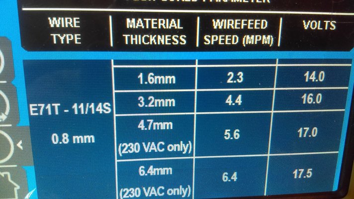
Flux core welding is a versatile welding process that can be used to weld a variety of metals. It is important to use the correct flux core welding settings to ensure that you get a good weld. The wrong settings can lead to defects such as porosity, slag inclusions, and undercut.
There are a number of factors that affect flux core welding settings, including:
Wire Diameter
- The diameter of the wire used for flux core welding is typically between 0.030 and 0.062 inches. The thicker the wire, the more heat it will generate and the faster it will travel.
- The wire diameter also affects the penetration of the weld. A thicker wire will produce a deeper weld than a thinner wire.
Shielding Gas
- The shielding gas used for flux core welding is typically a mixture of argon and carbon dioxide. The argon helps to protect the weld from oxidation, while the carbon dioxide helps to stabilize the arc.
- The flow rate of the shielding gas is also important. A too-low flow rate can lead to porosity, while a too-high flow rate can lead to undercut.
Travel Speed
- The travel speed of the welder is also important. A too-slow travel speed can lead to undercut, while a too-fast travel speed can lead to porosity.
- The travel speed should be adjusted based on the thickness of the metal being welded and the type of weld being made.
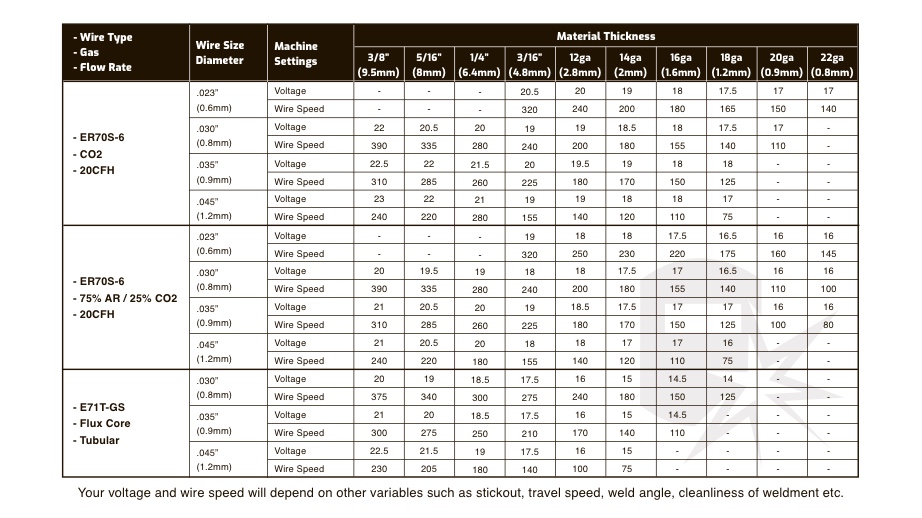
Flux Core Welding Settings Chart
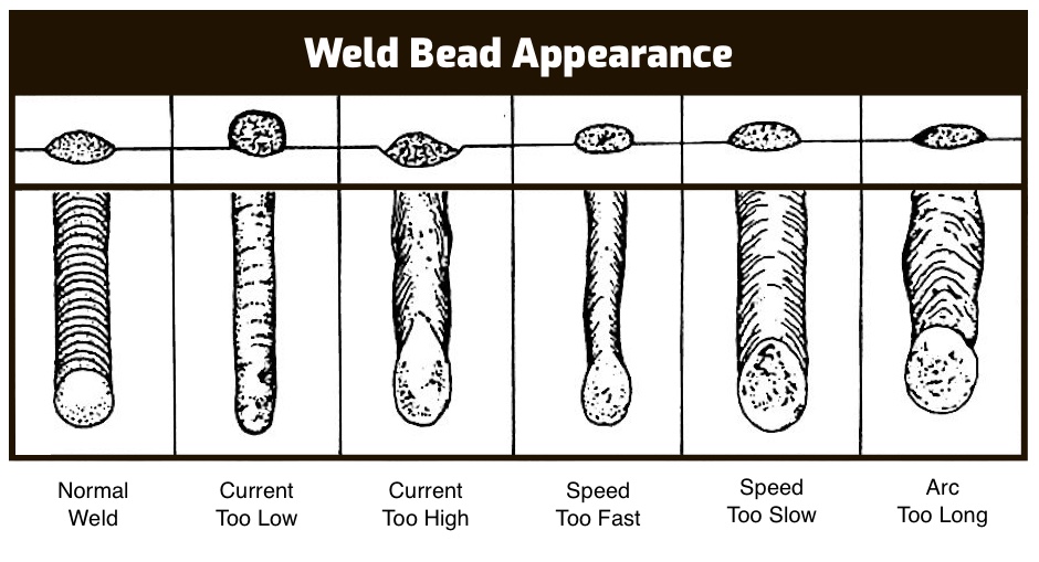
Flux Core Welding Settings Chart
This chart provides recommended settings for flux core welding, which is a type of arc welding that uses a continuously fed consumable electrode and a shielding gas to protect the weld pool from the atmosphere.
The chart includes the following information:
- Wire diameter
- Shielding gas
- Travel speed
- Voltage
- Wire feed speed
These settings can be used as a starting point for your own welding projects, but it is important to experiment with different settings to find what works best for your particular application.
| Wire Diameter | Shielding Gas | Travel Speed | Voltage | Wire Feed Speed |
|---|---|---|---|---|
| .030″ | C25 | 12-18 IPM | 18-22 Volts | 150-200 IPM |
| .035″ | C25 | 10-16 IPM | 20-24 Volts | 175-225 IPM |
| .045″ | C25 | 8-14 IPM | 22-26 Volts | 200-250 IPM |
Examples of Flux Core Welding Settings
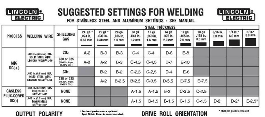
Flux core welding settings vary depending on the material thickness, type of metal, and desired weld quality. Here are some examples of flux core welding settings for different materials and applications:
Mild Steel
Wire diameter
0.035-0.045 inches
Voltage
22-28 volts
Wire feed speed
150-250 inches per minute
Travel speed
6-12 inches per minute
Shielding gas
None
Stainless Steel
Wire diameter
If you’re looking for a flux core welding settings chart, you can find a comprehensive one online. For example, the cerritos performing arts center seating chart website has a handy chart that you can use as a reference. Once you have your settings dialed in, you’ll be able to weld like a pro in no time.
0.030-0.045 inches
Voltage
20-26 volts
Wire feed speed
100-200 inches per minute
Travel speed
4-8 inches per minute
Shielding gas
Argon or argon-oxygen mix
Aluminum, Flux core welding settings chart
Wire diameter
0.030-0.040 inches
Voltage
18-24 volts
Wire feed speed
75-150 inches per minute
Travel speed
3-6 inches per minute
Shielding gas
Argon or helium-argon mix
Methods for Determining Flux Core Welding Settings

Flux core welding requires precise settings to achieve optimal weld quality. Various methods can be used to determine the appropriate settings, ensuring efficient and effective welding operations.
Welding Chart
Welding charts provide a convenient starting point for determining flux core welding settings. These charts typically list recommended settings for different material thicknesses, joint types, and welding positions. Using a welding chart can help avoid excessive trial and error, saving time and materials.
When tackling flux core welding projects, it’s essential to have the right settings for optimal results. Refer to a comprehensive flux core welding settings chart for guidance. Need to plan your seating arrangements for an upcoming event? Check out the welsh ryan arena seating chart for a visual representation of the venue’s seating layout.
Returning to flux core welding, always remember to adjust your settings based on the material thickness, wire diameter, and shielding gas used.
Experimentation
Experimentation is another method for determining flux core welding settings. This involves adjusting settings incrementally and observing the resulting weld quality. This method allows for fine-tuning the settings to suit specific welding conditions and materials. However, experimentation can be time-consuming and requires a skilled welder to interpret the results accurately.
Procedures for Adjusting Flux Core Welding Settings
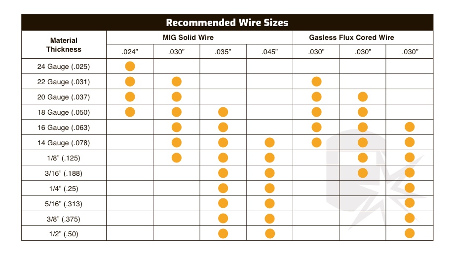
Adjusting flux core welding settings is crucial for achieving optimal weld quality. Follow these steps to ensure proper setup:
Wire Feed Speed
- Start with a recommended wire feed speed from the welding machine manual or manufacturer’s guidelines.
- Adjust the speed to obtain a stable arc with minimal spatter and a smooth bead appearance.
Voltage
- Begin with a suggested voltage range and fine-tune it to achieve a consistent arc length.
- A higher voltage results in a longer arc, while a lower voltage produces a shorter arc.
Travel Speed
- Set a travel speed that allows for complete fusion of the base metal without excessive heat input.
- Adjust the speed based on material thickness, joint design, and desired weld penetration.
Polarity
- Most flux core welding uses direct current electrode positive (DCEP), where the electrode is positive and the workpiece is negative.
- In some cases, direct current electrode negative (DCEN) may be used for specific applications or materials.
Shielding Gas
- Flux core welding does not require an external shielding gas, as the flux provides the necessary protection.
- However, some applications may benefit from the addition of an inert gas such as argon or carbon dioxide.
Other Settings
- Additional settings may include pre-flow and post-flow gas times, wire stick-out length, and inductance.
- Refer to the welding machine manual or manufacturer’s guidelines for specific recommendations.
Troubleshooting Flux Core Welding Settings

Flux core welding settings can sometimes cause problems, but these can usually be resolved by identifying the issue and making the necessary adjustments.
Common Problems and Troubleshooting Tips
*
-*Porosity
This can be caused by incorrect gas shielding, moisture in the flux, or dirty metal. Ensure proper gas flow, dry the flux before use, and clean the metal surface.
-*Spatter
This is caused by excessive voltage or wire feed speed. Reduce the voltage or wire feed speed, or increase the travel speed.
-*Incomplete fusion
This is caused by insufficient heat input. Increase the voltage or wire feed speed, or reduce the travel speed.
-*Undercut
This is caused by excessive heat input. Decrease the voltage or wire feed speed, or increase the travel speed.
-*Burn-through
This is caused by excessive heat input or too thin material. Decrease the voltage or wire feed speed, increase the travel speed, or use thicker material.
Illustrations of Flux Core Welding Settings

Flux core welding settings play a critical role in determining the quality and efficiency of the welding process. Understanding the effects of different settings allows welders to optimize their welding parameters and achieve desired results. Here are some detailed descriptions of illustrations or images that demonstrate the effects of different flux core welding settings:
Effect of Voltage on Weld Penetration
The voltage setting directly influences the depth of weld penetration. Higher voltage settings result in deeper penetration, while lower voltage settings produce shallower penetration. This is because higher voltage provides more electrical energy to the arc, which in turn generates more heat and melts more base metal, leading to deeper penetration.
Effect of Wire Feed Speed on Bead Width
The wire feed speed setting controls the amount of filler metal deposited per unit time. Higher wire feed speeds result in wider weld beads, while lower wire feed speeds produce narrower beads. This is because a higher wire feed speed supplies more filler metal to the weld pool, which increases the width of the deposited weld bead.
Effect of Travel Speed on Weld Appearance
The travel speed setting determines the rate at which the welding torch moves along the joint. Higher travel speeds result in flatter and wider weld beads, while lower travel speeds produce taller and narrower beads. This is because a higher travel speed reduces the amount of heat input per unit length of weld, resulting in a flatter and wider bead.
Effect of Shield Gas Flow Rate on Weld Quality
The shield gas flow rate setting controls the amount of shielding gas supplied to the weld area. Higher gas flow rates provide better shielding from atmospheric contaminants, resulting in cleaner and higher-quality welds. Lower gas flow rates may lead to porosity and other weld defects due to insufficient shielding.
.gallery-container {
display: flex;
flex-wrap: wrap;
gap: 10px;
justify-content: center;
}
.gallery-item {
flex: 0 1 calc(33.33% – 10px); /* Fleksibilitas untuk setiap item galeri */
overflow: hidden; /* Pastikan gambar tidak melebihi batas kotak */
position: relative;
margin-bottom: 20px; /* Margin bawah untuk deskripsi */
}
.gallery-item img {
width: 100%;
height: 200px;
object-fit: cover; /* Gambar akan menutupi area sepenuhnya */
object-position: center; /* Pusatkan gambar */
}
.image-description {
text-align: center; /* Rata tengah deskripsi */
}
@media (max-width: 768px) {
.gallery-item {
flex: 1 1 100%; /* Full width di layar lebih kecil dari 768px */
}
}

Our website has become a go-to destination for people who want to create personalized calendars that meet their unique needs. We offer a wide range of customization options, including the ability to add your own images, logos, and branding. Our users appreciate the flexibility and versatility of our calendars, which can be used for a variety of purposes, including personal, educational, and business use.

